
Water extraction from wells for irrigation and water supply
A well can provide water for a farm, greenhouse complex, nursery, production site, or remote facility not connected to a central network. However, having a source does not in itself guarantee a stable water supply.
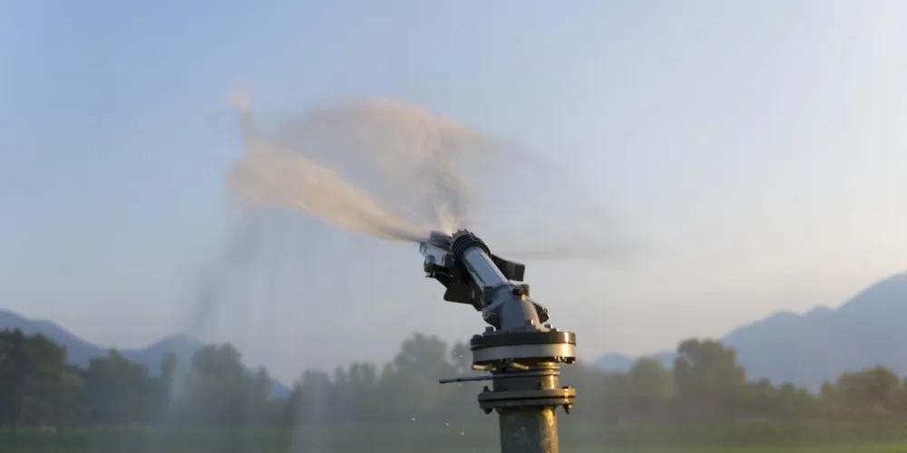
A well can provide water for a farm, greenhouse complex, nursery, production site, or remote facility not connected to a central network. However, having a source does not in itself guarantee a stable water supply. It is necessary to reconcile the well's capabilities with the facility's needs, correctly select a pump, and provide protection for the equipment.
Errors at the selection stage often manifest after startup. The pump may not generate the required pressure, cycle too frequently, extract water faster than it enters, or operate with increased energy consumption. Therefore, equipment is selected not only based on well depth and motor power, but on a combination of hydraulic, installation, and operational parameters.
What data must be obtained about the well
First of all, the well log and the results of test pumping should be studied. The documentation must specify the total depth, casing construction, filter placement, static and dynamic levels, and the allowable operational yield. If the information is outdated or the actual state of the source has changed, repeat measurements are taken before selecting equipment.
The static level shows the water position when pumping is stopped. The dynamic level is recorded during pumping at a specific capacity. For calculating the lift, the dynamic level is used as a reference because it reflects the conditions under which the pump will operate. The more intensive the water extraction, the lower the water may drop.
Yield should not be confused with pump capacity. Yield characterizes the well's ability to replenish extracted water, while pump flow shows the volume the unit moves per unit of time. If equipment systematically extracts more than the allowable operational yield, the level drops, and the risk of sand ingress and operation with insufficient motor cooling increases.
Before selecting equipment, it is advisable to gather the following information:
inner diameter of the casing and any constrictions;
well depth and position of the filter zone;
static and dynamic levels;
allowable operational yield;
chemical composition of the water and mechanical impurity content;
intended water extraction regime;
power supply parameters at the facility.
The actual inner diameter is especially important for old or complex wells. The nominal designation of the casing does not always reflect the minimum clearance throughout the entire depth. Joints, deformations, and irregularities can hinder the safe lowering and subsequent extraction of equipment.
How to calculate the required flow and head
The required flow is determined by actual water consumption. For irrigation, the number of simultaneously operating sprinklers, drip lines, or irrigation zones is taken into account. For a livestock facility, the consumption of drinkers, sanitary points, washing equipment, and other consumers that may operate simultaneously is summed up.
If water first enters a storage tank, pump capacity can be linked to the tank volume and the allowable filling time. Such a scheme allows for smoothing out peak loads and reconciling water extraction with the well's capabilities. During hours of peak consumption, the facility uses the stored water, and the pump replenishes it in a more uniform manner.
For water extraction from wells, it is necessary to calculate the total head. It includes the vertical difference between the dynamic level and the point of delivery, the required residual pressure at the consumer, and losses in pipelines, filters, valves, and other equipment.
The total length of the pipeline cannot simply be added to the well depth as additional height. The vertical drop forms the static component of the head, while the length, diameter, and material of the pipeline are used when calculating hydraulic losses. The higher the flow and the smaller the inner diameter of the pipe, the more significant the resistance in the network.
The model is chosen based on the operating point, where the design flow and head are simultaneously ensured. Maximum flow and maximum head in a catalog usually refer to different modes and are not achieved simultaneously. It is desirable that the operating point is in the recommended range of the performance curve, rather than at its extreme edge.
How to choose the size and material
The nominal size of a submersible pump is not equal to the well diameter. When checking for installation feasibility, the maximum cross-sectional dimensions of the entire unit, cable, cable channel, protective elements, and protruding parts are considered. There must be sufficient clearance between the equipment and the casing for lowering, extraction, and water flow along the electric motor.
Too small a clearance increases the risk of jamming. But excessively large space is not always beneficial: the flow rate around the motor housing may be insufficient for normal cooling. If the natural flow does not provide the required conditions, the design should include a special shroud that directs water along the motor.
The material of the flow path is selected considering the water chemistry, corrosion resistance requirements, and system parameters. Stainless steel versions are in demand when there are high requirements for corrosion protection. Cast iron models are used for industrial, municipal, and agricultural water intakes with high design water consumption. The final decision is made not only based on the facility's purpose but also on the results of water analysis.
When selecting well pumps, it is necessary to separately check the allowable temperature, mineralization, chloride content, pH, mechanical impurity concentration, and particle size. The intake screen traps large inclusions but does not protect the pump part from the prolonged impact of fine abrasive sand.
If sand appears in the water after startup, one should not simply replace the pump with a more powerful one. It is necessary to check the condition of the filter zone, the casing, the installation depth, and the actual pumping regime. An increased content of mechanical impurities often indicates a problem with the well or exceeding the allowable water extraction.
Installation, cooling, and pump position
The unit is installed below the dynamic level with sufficient immersion for stable flow and motor cooling. At the same time, restrictions regarding the bottom, filter part, and water intake zones are observed. The exact position is determined by the well log, the instructions for the chosen model, and the water intake project.
The pump should not be installed directly on the bottom. Sand and sediment may accumulate at the bottom of the well and enter the suction port. Placing it too close to the filter zone can also impair operating conditions, so safe distances should be verified against the specific equipment documentation.
The delivery pipeline is selected based on working pressure, installation depth, and equipment weight. The cable is secured along the pipe at specified intervals but should not be used to suspend the unit. Joints must withstand prolonged operation under load and allow for safe equipment extraction for maintenance.
The direction of water flow along the motor depends on the well design and the position of the inflow. If water enters above the pump or the equipment is installed in a tank or an open source, natural cooling may be insufficient. The need for a shroud is determined by calculation, taking into account flow rate, the diameter of the space around the motor, and the manufacturer's requirements.
Before startup, check electrical connections, insulation resistance, valve positions, the condition of the check valve, and the functionality of protections. The initial startup should be performed while monitoring pressure, flow, motor current, and dynamic level to confirm that the actual regime corresponds to the design parameters.
Automation and protection against emergency modes
The control system must consider the water supply method. When filling a tank, the pump can be turned on and off via level sensors. With direct supply to the network, control is usually built on pressure, and for variable flow, frequency regulation can be used.
Dry-running protection is especially important when water inflow is unstable. It must stop the motor before insufficient immersion leads to overheating or failure of the hydraulic part. Protection against overload, improper voltage, phase loss, or incorrect phase sequence should also be provided.
A frequency converter helps maintain the set pressure and change performance depending on current consumption. However, it does not eliminate the consequences of incorrect pump selection. It is necessary to check the allowable frequency range, minimum flow, cooling conditions, and operating points under different modes.
At facilities with continuous water consumption, redundancy should be considered. This could be a second pump ready for automatic activation, or a system with several units that distribute the load. The specific scheme is chosen based on the allowable interruption duration and the consequences of stopping the water supply.
For operational monitoring, it is useful to record initial parameters after startup: pressure, flow, current, dynamic level, and tank filling time. Comparing current indicators with the initial ones helps detect pipeline clogging, wear of the hydraulic part, or a change in the well condition.
What to monitor during operation
Even properly selected equipment requires regular observation. One should monitor water level, pressure, performance, motor current, and the presence of mechanical impurities. A sudden or gradual change in these indicators may indicate either a pump malfunction or a deterioration of the source condition.
Frequent starts reduce the service life of the electric motor and starting equipment. If the pump starts at short intervals, check the volume of the pressure tank, automation settings, network airtightness, and whether the performance corresponds to actual consumption.
A drop in pressure is not always related to wear of the pump part. The cause could be a leak, a clogged filter, a reduction in the internal passage of the pipeline, or a drop in the water level. Diagnostics should be carried out on the entire system, not just the unit.
For seasonal facilities, checks should be performed before the start of intensive operation. Inspect the control cabinet, cable connections, pipeline, valves, and measuring instruments. For year-round operation, establish a technical maintenance schedule and keep a parameter log.
Reliable water extraction is ensured not by the maximum power of the equipment, but by the coordination of the well, pump, pipelines, consumers, and automation. Calculation based on actual data helps maintain stable supply, not exceed the source's capabilities, and reduce costs for electricity and repairs.
Editorial team agronom.info
Materials are prepared by the portal's agronomists and editors. We use only trusted sources: Ukrainian agricultural universities, variety registries, open scientific publications.
Related articles
Not yet comments. Be the first!
Comments